|
TYPICAL OPERATING DATA |
|||||
|
Static Pressure (w.g. in) |
Motor HP |
Face Velocity (feet/minute) |
Blower Size |
Blower RPM |
Airflow CFM |
|
.1 |
.75 |
679 |
15 Wheel Dia |
470 |
4550 |
|
.2 |
.75 |
649 |
15 Wheel Dia |
485 |
4350 |
|
.3 |
.75 |
629 |
15 Wheel Dia |
513 |
4220 |
|
.4 |
.75 |
604 |
15 Wheel Dia |
540 |
4050 |
|
5 |
.75 |
575 |
15 Wheel Dia |
566 |
3850 |
|
.6 |
.75 |
548 |
15 Wheel Dia |
595 |
3670 |
|
.7 |
.75 |
522 |
15 Wheel Dia |
625 |
3500 |
|
.8 |
.75 |
496 |
15 Wheel Dia |
656 |
3320 |
|
.9 |
.75 |
467 |
15 Wheel Dia |
684 |
3127 |
|
1.0 |
.75 |
424 |
15 Wheel Dia |
712 |
2900 |
|
TYPICAL OPERATING DATA 2 |
|||||
|
Static Pressure (w.g. in) |
Motor HP |
Face Velocity (feet/ minute) |
Blower Size |
||
|
.1 |
.75 |
679 |
15 Wheel Dia |
||
|
.2 |
.75 |
649 |
15 Wheel Dia |
||
|
.3 |
.75 |
629 |
15 Wheel Dia |
||
|
.4 |
.75 |
604 |
15 Wheel Dia |
||
|
5 |
.75 |
575 |
15 Wheel Dia |
||
|
.6 |
.75 |
548 |
15 Wheel Dia |
||
|
.7 |
.75 |
522 |
15 Wheel Dia |
||
|
.8 |
.75 |
496 |
15 Wheel Dia |
||
|
.9 |
.75 |
467 |
15 Wheel Dia |
||
|
1.0 |
.75 |
424 |
15 Wheel Dia |
||
|
TYPICAL OPERATING DATA CONT. |
|||||
|
Static Pressure (w.g. in) |
Blower RPM |
Airflow CFM |
|||
|
.1 |
470 |
4550 |
|||
|
.2 |
485 |
4350 |
|||
|
.3 |
513 |
4220 |
|||
|
.4 |
540 |
4050 |
|||
|
5 |
566 |
3850 |
|||
|
.6 |
595 |
3670 |
|||
|
.7 |
625 |
3500 |
|||
|
.8 |
656 |
3320 |
|||
|
.9 |
684 |
3127 |
|||
|
1.0 |
712 |
2900 |
|||
Note the impact of static pressure load on blower RPM which results in changing airflow. The air velocity is based on a cooler with a 6.7 square feet opening. Shaded area indicates undesirable operating range.
What is the best way to balance the Blower and Motor to achieve the best performance of the Cooler?
The simple answer is to control the air velocity through the cooling media to not exceed 550 feet per minute. When the air flow velocity exceeds 600 feet per minute, there is a high probability that raw moisture can be pulled off the back of the media and entrained in the air flow into the duct work and/or into the structure being cooled.
How can the air velocity be controlled?
The speed (RPM) of the Blower determines the volume of air flow which is measured in Cubic feet per minute with the size of the opening (measured in square feet) through which the air flows determines the air velocity.
Air velocity is measured with a velocity meter (velometer). The adjustable motor pulley is adjusted to alter the RPM of the blower to achieve the desired air velocity. This method controls the air volume to the limitations of the duct system pressure (static pressure of the air delivery system).
Why is the method of adjusting the motor load to the nameplate amperage rating not recommended as a way to determine the proper adjustment of the motor drive.
The motor may be too large for the application and will drive the blower too fast causing an excessive air volume and velocity. The properamperage load for an oversized motor may be considerably belowthe nameplate rating.
How do you adjust the RPM of the Blower?
The motor pulley is adjustable (or should be) to permit changing the ratio of RPM of the Motor to the RPM of the Blower. I.E. If the motor pulley is 3 diameter and the blower pulley is 9 diameter, you have a 3:1 ratio. This means the motor pulley will turn 3 times that of the blower. Assuming a 1725 RPM (generally standard in the USA) of the motor, the blower would be turning at 575 RPM.
Adjusting the motor pulley to a different diameter would change the blower RPM accordingly. Making the motor pulley smaller would slow down the blower and conversely, making the motor pulley larger would speed up the blower RPM.
Some installers approach the adjusting of the blower RPM with the attitude that faster is better and the more air flow, the better. This is not the proper procedure to use and can be detrimental to the function of the cooler.
What are some of the ramifications of improper blower RPM?
When the blower is moving too much air flow causing the air velocity to go over 600 feet per minute, there is a high probability that raw moisture (water) will be pulled off the cooling media and entrained in the air flow.
Another factor is that the cooling performance decreases as air velocity increases. I.E. at 400 feet per minute velocity, 12 cooling media performs at 92% efficiency while at 550 FPM, the performance is 88%. This cooling performance equates to 2 or 3 degree colder air difference.
What is the proper alignment of rigid cooling media?
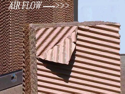 As you can see in the picture of rigid cooling media, there are 2 different flute alignments. There is a 150 flute and a 450 flute. The air flow direction is in at the bottom of the 450 flute and the top of the 150 flute. The air flow moves through the 150 flute and the water flows downward through the 450 flute. The air flow pushes the water into the media causing it to become saturated. The bypass action of the air through one flute and the water through the other causing cooling to be maximized. Water flows through the 450 flute to the face of the media and excess water into the sump.
Note: if the media is installed backwards, water will flow to the discharge side which is the most common cause of water carry over into the duct system.
How do you adjust water flow over the cooling media?
There is either a clamp or valve in the riser pipe (water line from the pump to the header pipe over the media) included to meter water flow.
How much water is needed for the media to be properly saturated (wetted)
The ideal amount of water over the media is a flow rate equal to the amount lost to evaporation plus an additional amount to “wash the media. This “wash water is needed to help clean the media by allowing some water to flow through the media and into the sump.
Unfortunately, the evaporation rate changes constantly with change in temperature and/or humidity. During low humidity periods, the evaporation rate will be high and at high humidity periods, the evaporation rate will be low. The water use will vary inversely with humidity and temperature changes. Cooling efficiency will also vary inversely with changes in humidity. IE. Low efficiency during high humidity and high efficiency during low humidity.
Only pure water evaporates which leaves the minerals behind on the face of the media and in the sump. In order to reduce this build up effect, a “bleed-off amount of water will be fed into the drain system to force fresh water to replace it in the sump.
The cooling media requires a break-in period of several hours before it properly saturates with water. This period usually ranges from about 6 to 12 hours of operation. In setting the water flow over the media, it is important to take this initial wetting process into consideration.
The best estimation of water flow rate is about 1/2 G PM for each square foot of top surface area of the Media. This means that a 4 foot wide section of 12 deep media would be set at about 2 GPM total flow. This typical for a hot, dry climate such as Phoenix, AZ. The flow rate would be less in a milder climate.
Note: Too much water flow over media can cause over saturation and allow water to be pulled off the back side of the media and into the duct system
What effect does water quality have on evaporative cooling?
Water quality is usually measured to determine the pH level. pH is the measure of how acidic the water is. The range of pH is 0 “ 14 with 7 being neutral. The desired range of water pH for cooling media is 6 “ 8. Acidity is considered “hard water with the salinity content being the worse offender. High pH would indicate water with high mineral (salinity) which would be left behind on the face of the media causing an unwanted build up blocking air flow and deterioration of the cooling media. Most water supply in the Southwest is heavily alkaline which is a form of salinity. We refer to it as “salts or “calcium which is all in the same family of minerals. Build up of these minerals on the face of the media reduces the useful life of the media.
Cooling efficiency is also adversely affected by poor water quality. The higher the mineral content in the water, the lower the evaporation rate resulting in lower cooling efficiency.
Treated water below the 6 pH level can also be harmful to the media in that it can “leach out some of the saturants and chemicals used in bonding the media. This is usually not a serious concern but can have a minimal effect on useful life of the media.
What is the recommended process for winterization of the cooler?
The cooling media should be inspected for possible replacement. The header pipe should be flushed out and any orifice holes that are clogged should be cleared. The cooling media, if not to be replaced, can remain in the unit provided a blank-off panel is used to block any airflow through the unit.
The PremierCool Residential Cooler is provided with a blank-off panel that can be placed in front of the media to close off the intake. This prevents cold air from passing through the unit as well as protecting the media and preventing debris from accumulating inside the wet section.
The supply water should be shut off. The unit should be drained and the drain left open to empty any water coming into the unit. The pump should be removed from the wet section and not be allowed to sit in water. It can be set in the blower housing.
There is no specific recommendation for the blower section except to inspect the blower for any obvious damage and check the drive belts for condition and proper tension. The unit should be shut down electrically so it cannot be started inadvertently.
Start up procedures
The cooler should be inspected for any visible damage that might affect operation. The blank-off panel (if used) can be removed. The sump should be cleaned out. The drain should be replaced and the sump supply water turned on to refill the sump. The pump should be tested by hand turning the shaft to the impeller. If it is free, the pump can be replaced in the sump. The hose connections to the header pipe should be ready for use unless they were removed during the winter shut down. The cooling media and header pipe should be ready for use, assuming the winter shut down included the recommended cleaning and inspection.
The blower section should be checked for motor drive belts condition and tension. Electrical power can be turned on and the unit tested for proper operation.